Blog_3
08 May 2019
Building the project - Part 1
Once we have designed every component of our project and tested its functionality, it was time to put it all together. In order to do this, we first designed a prototype of a rig using solidworks to simulate what it could actually look like. The following image is a CAD of the prototyped which we would lasercut using acrylic:
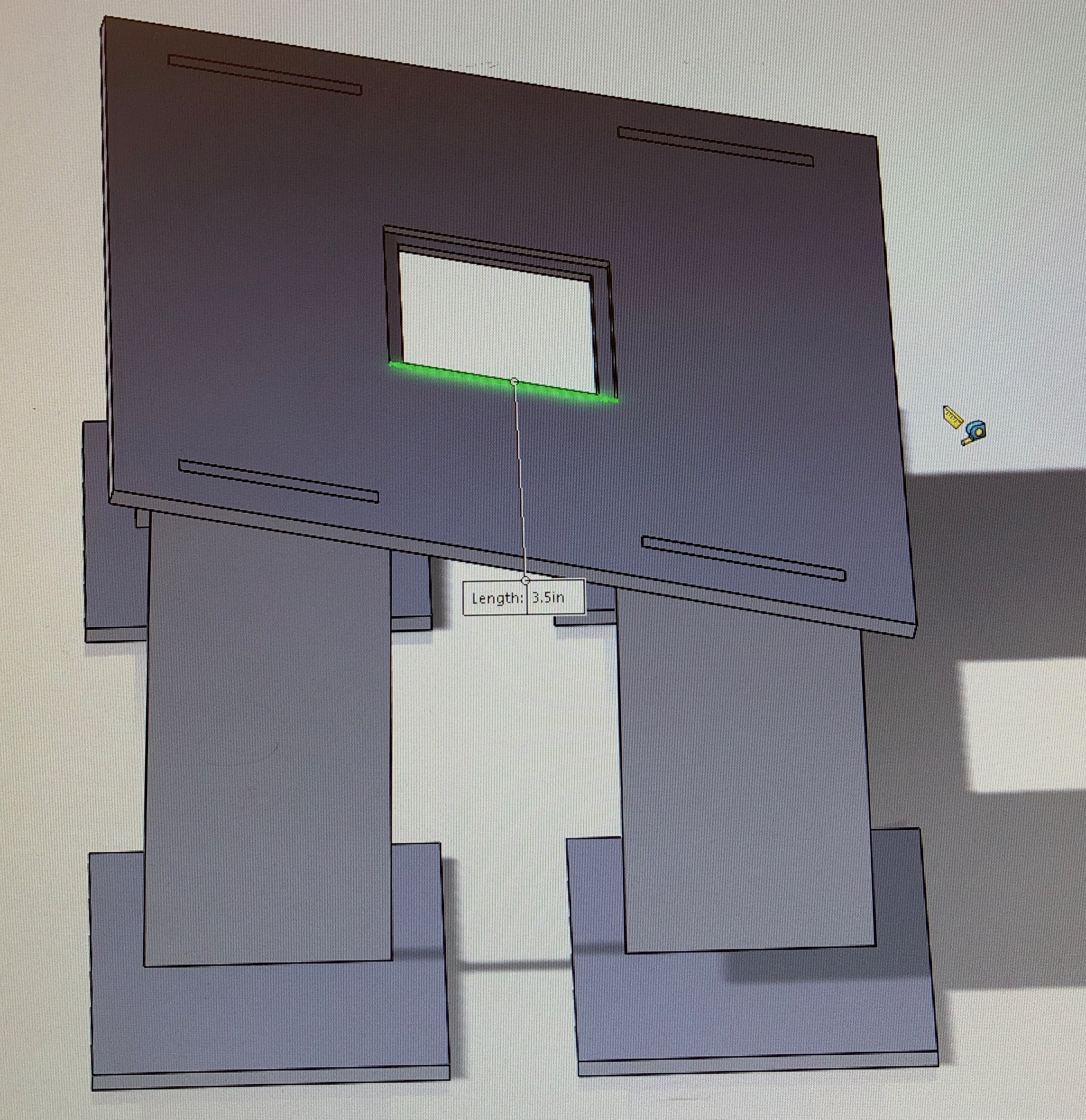
With this design, we could easily attach a square grip to the hole for any size implant. We also will have enough room to attach the circuitry required for the force and displacement sensor.
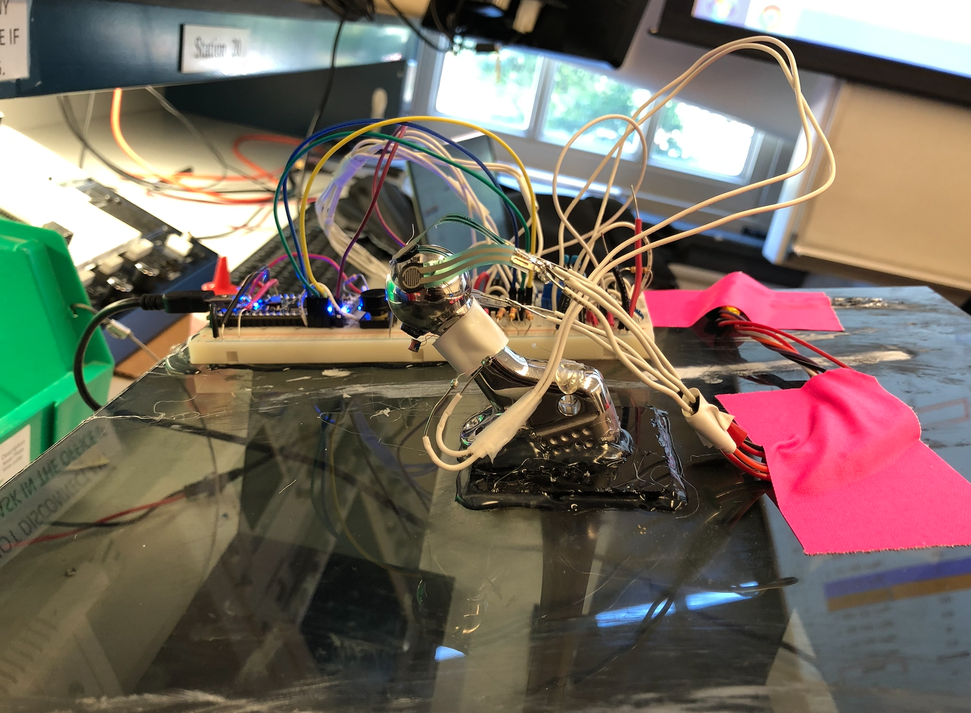
For the force sensor component, our goal was to create a cheap, multiaxial force sensor. In order to implement this, we used 3 force-sensitive resistors that would be attached to the femoral head. On top of the resistors would be a spherical shield that,when pressure was applied, would deflect and varying pressure to the three resistors based on the location of the force. Hence, we decided to 3D print this spherical shell that would not only withstand the force of a hammer but also deflect upon applied pressure and retain its shape. A material called NinjaFlex worked perfectly for this task.
Building the project - Part 2
For our reach demo, we were able to transfer the circuitry from a breadboard to a PCB. Furthermore, we designed an actuator component that would stimulate micromotion along the femoral head. For this demonstration, we decided to translate rotational motion (coming from a servo) into linear motion onto the femoral head in order to stimulate the micromotion. The following image is a CAD for this component:
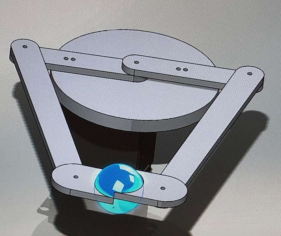
The whole actuator was built by lasercutting the pieces using acrylic.
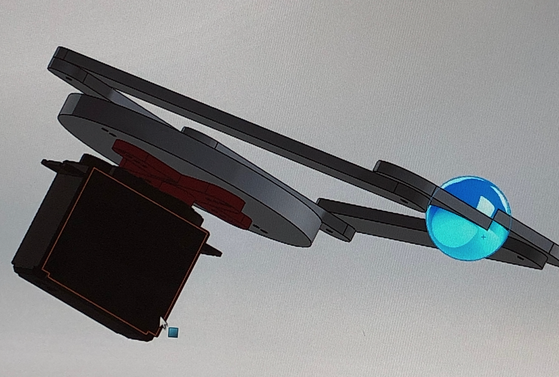
The following image is a side view of our final project: