Blog_1
19 Apr 2019
The Motivating Problem
One of the biggest problems in orthopedic hip implant surgery is the so-called “taper disaster.” A hip implant looks like this:
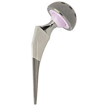
It is composed of an acetabular cup, which is implanted against the acetabulum on the hip. This is where the implant is physically held in place in the hip. The acetabular cup acts as a socket for the femoral head, which is the pink ball shown above. This is where the joint action actually occurs. The femoral head is connected to the femoral stem, which is implanted into the femur. The femoral head and stem are held together by a male and female taper, which looks like the below image:
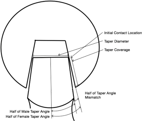
This taper has an angle mismatch, which is small but non-negligible. Over time, the continuous force applied to the femoral head by the weight of standing causes unintended micromotion between the male and female taper. Since the femoral head is metallic, this micromotion creates some debris which accumulates over time. Metal debris in the fluid around the hip can cause toxicity and lead to revision surgery, where the hip implant is replaced in a second round of surgery. In fact, this taper mismatch and corresponding metallic debris is a major cause of hip revision surgery, which is why the problem has been called the “taper disaster” by some researchers. Research by Mroczkowski, et al. has shown that the impact assembly force of a modular hip implant (like the one shown above) causes different levels of corrosion. Our goal in this project is to design a testing rig which can estimate the rate of corrosion based on the level of micromotion, and help a surgeon fine-tune the level of assembly force required for a given hip implant to minimize micromotion—and thus reduce the rate of corrosion.
Displacement Sensor
The biggest sensor challenge in this project is designing a displacement sensor that is able to detect micromotion. Our approach is to design a circuit which translates small changes in inductance to detectible changes in frequency, in an approximately linear fashion. To accomplish that, the following circuit is used:


The main sensor portion of the circuit is simply an LC resonant tank. The resonant frequency depends on the impedance of the inductor (assuming constant impedance from the capacitor). The inductor’s impedance varies in the presence of a magnetic field, and since the inductor is a coil it produces its own magnetic field. When a conductor is moved close to the inductor, the magnetic field of the inductor generates Eddy Currents in the conductor, which in turn create an opposing magnetic field by Lenz’s Law. This changes the impedance of the inductor, and the effect grows in magnitude the closer the conductor is to the inductor. The LC resonant tank is then connected to a buffer in feedback. This buffer actively drives a square wave output at a frequency directly proportional to the resonant tank frequency. It then feeds back into the resonant tank, actively driving the tank to prevent dampening. As a result, the waveform at C4 is a square wave with frequency related to the inductance of the inductor. The waveform then moves to a frequency multiplier stage, in order to make the frequency difference easier to detect by the microcontroller. The multiplier works by the principle of superposition. The waveform from the inverter and the pseudo-inverter superimpose and cancel between 2-3 times per cycle depending on the tuning of the resistors and capacitor. As a result, the frequency multiplier cuts into a waveform to produce approximately 3x the number of peaks and troughs—tripling the frequency. It then moves to a high-pass output filter and a final output buffer (since the signal is inverted prior to the highpass filter) At first trial, the sensor can detect motion about as small as 1-5mm. To improve it, an inductor with a higher Q factor and smaller diameter is required. Once micromotion can be detected, the inductive sensor will be placed in a position where it can detect taper motion, potentially by boring a hole through the femoral head:
.png)
An axial load will be placed on the head to stimulate motion, some of which will be taper micromotion. The magnitude of taper micromotion should depend on the assembly force measured by our multi-axial force sensor.
List of Components:
- 3x ALD1103 transistor arrays
- 4x 4.7kΩ resistor
- 100mH inductor
- 1pF capacitor
- 6x 10nF capacitors
- 1x 10MΩ resistor
- 1x 10mH inductor